Atari 8-bit Display List Interrupts: A Complete(ish) Tutorial
Revision 8, updated 28 Dec 2019
This is a tutorial on Display List Interrupts (DLIs) for the Atari 8-bit series of computers. In a nutshell, DLIs provide a way to notify your program when a particular scan line is reached, allowing you to make changes mid-screen.
No prior knowledge of DLIs is necessary before reading this tutorial. However, DLIs are an advanced programming technique in the sense that they require knowledge of 6502 assembly language, so this tutorial is going to assume that you are comfortable with that.
All the examples here are assembled using the MAC/65-compatible assembler ATasm (and more specifically to this tutorial, the version built-in to Omnivore).
Note
All source code and XEX files are available in the dli_tutorial source code repository on github.
Note
This tutorial is Copyright © 2019 and licensed under the CC BY-SA 4.0, except for the assembly language source code (both in this tutorial and in the repository), which is placed in the public domain via CC0.
Before diving into DLIs, it is helpful to understand that they are very accurately named: Display List Interrupts literally interrupt the display list – they cause an event that is processed by your program as the computer is in the middle of drawing the screen. So it is necessary to understand what display lists are before understanding what it means to interrupt one, and even before that we must understand how the Atari uses the display list to generate the images shown on the screen.
See also
Here are some resources for learning more about display list interrupts:
Displays: A Tiny Overview of How TVs Work
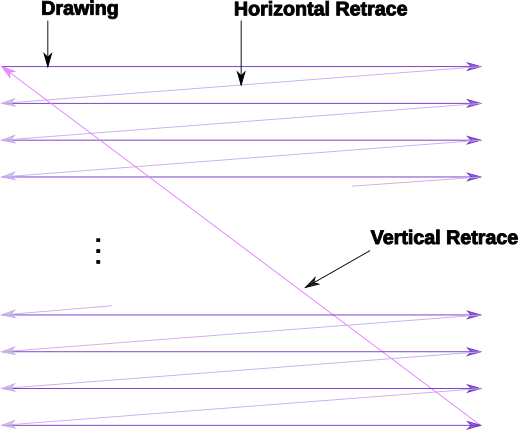
A TV screen is drawn by an electron beam tracing a path starting above the visible area, and drawing successive horizontal lines as the beam moves down the screen. Each line is drawn from left-to-right (as you look at the TV screen) and when it reaches the right hand side of the screen, the horizontal retrace starts where the beam is turned off and moved down to the next scan line below whereupon the beam is turned back on and the next line draws. When the full frame has been drawn, the beam is turned off again and the vertical retrace starts (starting the vertical blank interval). Once the beam is repositioned to the top leftmost position, the vertical blank interval ends, the beam is turned back on, and the next frame is started.
On NTSC systems, the Atari draws 262 scan lines per frame, 60 times per second. On PAL systems it draws 312 scan lines per frame, 50 times per second. In either system, it draws scan lines from the top down, and left to right within a scan line.
This simplified description is the mental model we will use to describe the video drawing process. Real TVs are much more complicated, but for the purposes of this tutorial are not important. The Atari was constrained to produce images that rendered on the displays of the time, but the details of how each type of display works (e.g. interlaced TV vs progressive scan monitor) doesn’t affect the signal output by the Atari.
One detail of color production is worth mentioning: a unit called the color clock, which is the smallest portion of a scan line that can be displayed with an arbitrary color. There are 228 color clocks per scan line, of which about 160 were typically visible on a cathode-ray TV display in the 1970s when the Atari was developed. This corresponds to the 160 pixel horizontal resolution of Antic Modes B through E in the standard width playfield. Antic Mode F (Graphics 8 in BASIC) has 320 addressable pixels, corresponding to half a color clock, and only artifacting color is available.
Color clocks also form the basis for the operating speed of the entire machine. For NTSC, the speed was chosen based on the use of a commonly available hardware component in use for TV displays, called an NTSC oscillating crystal. This component generates a pulse with a frequency of 14.31818 MHz. This frequency was then divided by eight to produce the 1.7897725 MHz clock at which the 6502 runs. By defining one CPU cycle to correspond to two color clocks, means there are 114 machine cycles per scan line. 262 scan lines per frame results in 29868 machine cycles every frame. And running at 1.7897725 Mhz means there are 1789772.5 machine cycles happening every second, which produces a frame rate of 59.92 Hz which can be displayed on a TV (even if it does not exactly sync up with broadcast NTSC).
PAL systems produce the same 228 color clocks and 114 machine cycles per line, but display 312 scan lines. This results in 35568 cycles per frame. The PAL crystal oscillates with a frequency of 14.18757 MHz, divided by 8 to produce a CPU frequency of 1.77344625 Mhz, and 35568 cycles per frame produces a frame rate of 49.86 Hz; again, not syncing exactly with broadcast PAL but within tolerances to be displayed.
See also
NTSC Demystified, (haha), a very long series of blog posts describing NTSC encoding
Obligatory link to the NTSC article on Wikipedia
Composite artifact colors article on Wikipedia
Section 4.2 in the Altirra Hardware Reference Manual (PDF) for much more technical detail and far, far less hand-waving.
Discussion on NTSC pixel clocks and timing at retrocomputing.stackexchange.com
Display Lists: How the Atari Generates the Display
ANTIC is the special coprocessor that handles screen drawing for the Atari computers. It is tightly coupled with the 6502 processor, and in fact can be thought of as being the driver of the 6502 because the ANTIC can halt the 6502 when needed. Since only one chip can read memory at any time, ANTIC needs to halt the 6502 when it needs access to memory, so this Direct Memory Access (DMA) can cause 6502 instructions to appear to take more cycles than documented in a 6502 reference. In fact, the amount of time ANTIC “steals” will depend on many factors: the graphics mode, player/missiles being used, playfield size, and more.
Since there are 228 color clocks and 114 machine cycles per scan line, this means that in one machine cycle, two color clocks are drawn on the screen. A typical machine instruction might take 5 machine cycles, so 10 color clocks could pass in the time to process a single instruction! This means we don’t have much time per scan line, so DLIs that attempt to change graphics in the middle of a line will have to be well optimized.
It also means the 6502 is too slow to draw the screen itself, and this is where ANTIC’s special “instruction set” comes in. You program the ANTIC coprocessor using a display list, and ANTIC takes care of building the screen scan line by scan line, without any more intervention from the 6502 code. (Unless you ask for intervention! And that’s what a DLI is.)
The display list is the special sequence of bytes that ANTIC interprets as a list of instruction. Each instruction causes ANTIC to draw a certain number of scan lines in a particular way. A DLI can be set on any ANTIC instruction.
ANTIC supports display lists that produce at most 240 scan lines (even on PAL systems where many more scan lines are available), and the vertical blank interval always starts after 248 scan lines. When drawing scan lines, ANTIC skips 8 scan lines at to top of the display, so the output from the display list starts at the 9th scan line. A standard display list starts with 24 blank lines and 192 scan lines of display data, meaning that the TV will see 32 blank lines (the 8 automatically skipped plus the 24 in a standard display list) followed by 192 scan lines of display, then 24 blank lines, and finally the vertical blank that consumes the remaining 14 scan lines on NTSC (or 64 on PAL).
Display List Instruction Set
An ANTIC display list instruction consists of 1 byte with an optional 2 byte address. There are 4 types of instructions: blank lines, text modes, bitmap graphic modes, and jump instructions. Instructions are encoded into the byte using a bitmask where low 4 bits encode the instruction type and the high 4 bits encode the flags that affect that instruction:
7
6
5
4
3
2
1
0
DLI
LMS
VSCROLL
HSCROLL
Mode
The 4 flags are:
DLI (
$80): enable a display list interrupt when processing this instructionLMS (
$40): trigger a Load Memory Scan, changing where ANTIC looks for screen data, and requires an additional 2 byte address immediately following this instruction byte.VSCROLL (
$20): enable vertical scrolling for this mode lineHSCROLL (
$10): enable horizontal scrolling for this mode line
There are 6 text modes and 8 bitmap graphic modes for a total of 14 modes, and are encoded into low 4 bits using values as shown in these tables:
Mode |
Decimal |
BASIC Mode |
Description |
Scan Lines |
Colors |
2 |
02 |
0 |
40 x 24 |
8 |
2 |
3 |
03 |
n/a |
40 x 19 |
10 |
2 |
4 |
04 |
n/a |
40 x 24 |
8 |
4 |
5 |
05 |
n/a |
40 x 12 |
16 |
4 |
6 |
06 |
1 |
20 x 24 |
8 |
5 |
7 |
07 |
2 |
20 x 12 |
16 |
5 |
Mode |
Decimal |
BASIC Mode |
Description |
Scan Lines |
Colors |
8 |
08 |
3 |
40 x 24 |
8 |
4 |
9 |
09 |
4 |
80 x 48 |
4 |
2 |
A |
10 |
5 |
80 x 48 |
4 |
4 |
B |
11 |
6 |
160 x 96 |
2 |
2 |
C |
12 |
n/a |
160 x 192 |
1 |
2 |
D |
13 |
7 |
160 x 96 |
2 |
4 |
E |
14 |
n/a |
160 x 192 |
1 |
4 |
F |
15 |
8 |
320 x 192 |
1 |
2* |
*mode F is also used as the basis for the GTIA modes (BASIC Graphics modes 9, 10, & 11), but this is a topic outside the scope of this tutorial.
Blank lines are encoded as a mode value of zero, the bits 6, 5, and 4 taking the meaning of the number of blank lines rather than LMS, VSCROLL, and HSCROLL. Note that the DLI bit is still available on blank lines, as bit 7 is not co-opted by the blank line instruction.
Hex |
Decimal |
Blank Lines |
0 |
0 |
1 |
10 |
16 |
2 |
20 |
32 |
3 |
30 |
48 |
4 |
40 |
64 |
5 |
50 |
80 |
6 |
60 |
96 |
7 |
70 |
112 |
8 |
Jumps provide the capability to split a display list into multiple parts in different memory locations. They are encoded using a mode value of one, and require an additional 2 byte address where ANTIC will look for the next display list instruction. If bit 6 is also set, it becomes the Jump and wait for Vertical Blank (JVB) instruction, which is how ANTIC knows that the display list is finished. The DLI bit may also be set on a jump instruction, but if set on the JVB instruction it triggers a DLI on every scan line from there until the vertical blank starts on the 249th scan line.
Note
Apart from the $41 JVB instruction, splitting display lists using other
jumps like the $01 instruction is not common. It has a side-effect of
producing a single blank line in the display list.
The typical method to change the currently active display list is to change the
address stored at SDLSTL (in low byte/high byte format in addresses
$230 and $231). At the next vertical blank, the hardware display list
at DLISTL ($d402 and $d403) will be updated with the values stored
here and the screen drawing will commence using the new display list.
See also
More resources about display lists are available:
A Sample Display List
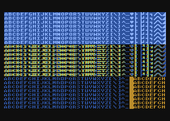
Here is a display list that contains different text modes mixed in a single screen.
- Source Code: sample_display_list.s
- Executable: sample_display_list.xex
dlist   .byte $70,$70,$70  ; 24 blank lines
        .byte $46,$00,$40  ; Mode 6 + LMS, setting screen memory to $4000
        .byte 6            ; Mode 6
        .byte $70          ; 8 blank lines
        .byte 7,7,7,7,7    ; 5 lines of Mode 7
        .byte $70          ; 8 blank lines
        .byte 2            ; single line of Mode 2
        .byte $70,$70,$70  ; 24 blank lines
        .byte 2,4          ; Mode 2 followed by mode 4
        .byte $70          ; 8 blank lines
        .byte 2,5          ; Mode 2 followed by mode 5
        .byte $41,<dlist,>dlist ; JVB, restart same display list on next frame
Cycle Stealing by ANTIC
The ANTIC coprocessor needs to access memory to perform its functions, and since the 6502 and ANTIC can’t both access at once, ANTIC will pause execution of the 6502 when it needs to read memory. It happens at specific points within the 114 cycles of each scan line, but where it happens (and how many times the 6502 gets paused during the scan line) depends on the graphics mode.
For overhead, ANTIC will typically steal 3 cycles to read the display list, 5 cycles if player/missile graphics are enabled, and 9 cycles for memory refreshing. Scrolling requires additional cycle stealing because ANTIC needs to fetch more memory.
Bitmapped modes (modes 8 - F) have cycles stolen corresponding to the number of bytes per line used in that mode. For example, mode E will use an additional 40 cycles, so in the context of writing a DLI for a game, the typical number of stolen cycles could be 57 out of the 114 cycles per scan line: 17 cycles for ANTIC overhead and 40 for the number of bytes per line.
Text modes require additional cycles over bitmapped graphics modes, because ANTIC must fetch the font glyphs in addition to its other work. The first scan line of a font mode is almost entirely used by ANTIC and only a small number of cycles is available to the 6502. For normal 40-byte wide playfields, the first line of ANTIC modes 2 through 5 will yield at most about 30 cycles and subsequent lines about 60 cycles per scan line.
About the worst-case scenario is one of the best modes for games: ANTIC mode 4. This text mode, combined with scrolling and player/missile graphics and can reduce the available cycles to fewer than 10 on the first line and about 50 on subsequent lines!
See also
Section 4.14 in the `Altirra Hardware Reference Manual (PDF)<http://www.virtualdub.org/downloads/Altirra%20Hardware%20Reference%20Manual.pdf>`_ contains tables depicting exactly which cycles are stolen by ANTIC for each mode.
Restrictions
display lists cannot cross a 1K boundary
display list data cannot cross a 4k boundary, so you must use a display list command with the
LMSbit if using a bitmapped display mode that will result in a larger memory usage
Display List Interrupts: A Crash Course
DLIs are non-maskable interrupts (NMIs), meaning they cannot be ignored. When
an NMI occurs, the 6502 jumps to the address stored at $fffa, which points
to an OS routine that checks the type of interrupt (either a DLI or a VBI) and
vectors through the appropriate user vector. The NMI handler takes care of
saving the processor status register and sets the interrupt flag, but does
not save any processor registers. The user routine is responsible for saving
any registers that it uses, restoring them when it is done using them, and must
exit using the RTI instruction.
Display list interrupts are not enabled by default. To use a DLI, the address
vector at VDSLST ($200 and $201) must be set to your routine, and
then they must be enabled through a write to NMIEN at $d40e.
Warning
You must set the address of your DLI before enabling them, otherwise the DLI
could be called and use whatever address is stored at $200.
This initialization code can look like the following, where the constants
NMIEN_VBI and NMIEN_DLI are defined as $40 and $80,
respectively, in hardware.s in the sample repository. Since NMIEN also
controls the vertical blank interrupt, you must make sure that the VBI enable
flag is also set.
; load display list interrupt address
lda #<dli
sta VDSLST
lda #>dli
sta VDSLST+1

; activate display list interrupt and vertical blank interrupt
lda #NMIEN_DLI | NMIEN_VBI
sta NMIEN
If your program has multiple DLIs, it may be necessary to set your DLIs in a
vertical blank interrupt to guarantee that ANTIC will process them in the
right order. Outside the VBI, your code could be running at an arbitrary scan
line, perhaps between display list instructions that have their DLI bits set.
In Yaron Nir’s tutorial a different technique is used, one not requiring a
vertical blank interrupt but instead using the RTCLOK 3-byte zero page
variable to instead infer that a VBI has just occurred. The last of the
bytes, location $14, is incremented every vertical blank, so that
technique is to wait until location $14 changes, then set NMIEN:
        lda RTCLOK+2
?loop   cmp RTCLOK+2  ; will be equal until incremented in VB
        beq ?loop

        ; activate display list interrupt and vertical blank interrupt
        lda #NMIEN_DLI | NMIEN_VBI
        sta NMIEN
Hardware & Shadow Registers
The Atari is a memory-mapped system, where hardware devices like the ANTIC and GTIA chips are mapped to locations in memory and data is passed back and forth by reading or writing to specific addresses. They are usually either read-only or write-only, and many times an address is used for wildly different features depending on whether the address is read from or written to.
Some of these hardware locations also have shadow registers in low RAM (typically page 2) that are labeled as performing the same function as a hardware register, with two important differences.
First, they can be both read and written to, so (assuming you always use the shadow register to update the hardware register) it is possible to find out the current state of a hardware register by reading its shadow.
Second, the hardware register is only updated once every vertical blank by an operating system routine that copies the shadow value to its hardware counterpart. Note that it does not happen the other way around, so changing a hardware register does not update a shadow register.
The shadow registers are a convenience for development in higher level languages like BASIC where speed is not paramount. But code within a DLI must use hardware registers directly to affect change on a scan line.
The shadow registers can still be useful in DLI development, in that they will automatically reset the hardware registers to the values in the shadow registers every vertical blank. This can be used to reset features like graphics colors and the character set address for the top of the screen at the next frame.
Note
This only works if the operating system’s immediate vertical blank routine has not been replaced (i.e. you are only using the deferred vertical blank VVBLKD at $224 and haven’t replaced the immediate vertical blank rountine VVBLKI at $222).
Some hardware registers have no shadows, like player position and size, so your own code (in the deferred VBI or the final DLI) must reset these to their correct values for the top of the screen.
Shadow |
Hex |
Hardware |
Hex |
Description |
GPRIOR |
26f |
PRIOR |
d01b |
Player/playfield priority selection register |
PCOLR0 |
2c0 |
COLPM0 |
d012 |
Color of player/missile 0 |
PCOLR1 |
2c1 |
COLPM1 |
d013 |
Color of player/missile 1 |
PCOLR2 |
2c2 |
COLPM2 |
d014 |
Color of player/missile 2 |
PCOLR3 |
2c3 |
COLPM3 |
d015 |
Color of player/missile 3 |
COLOR0 |
2c4 |
COLPF0 |
d016 |
Color of playfield 0 |
COLOR1 |
2c5 |
COLPF1 |
d017 |
Color of playfield 1 |
COLOR2 |
2c6 |
COLPF2 |
d018 |
Color of playfield 2 |
COLOR3 |
2c7 |
COLPF3 |
d019 |
Color of playfield 3 |
COLOR4 |
2c8 |
COLBK |
d01a |
Background color |
CHACT |
2f3 |
CHACTL |
d401 |
Character mode (inverse, upside-down characters) |
CHBAS |
2f4 |
CHBASE |
d409 |
Character base (page number of font) |
Basic Display List Interrupts
Our First Display List
A common use of display lists is to change colors in the middle of the screen.
- Source Code: first_dli.s
- Executable: first_dli.xex
Here is our first display list interrupt:
dli     pha             ; only using A register, so save old value to the stack
        lda #$7a        ; new background color
        sta COLBK       ; store it in the hardware register
        pla             ; restore the A register
        rti             ; always end DLI with RTI!
This is all the code it takes to change the color of the background. The obvious effect is the flickering line in the background, which we will solve in the next section.
Examining the code shows the boilerplate discussed above where DLIs always end with the RTI instruction
and any registers used must be saved before your code changes them, and
restored upon exit.
The work performed in the interrupt is just two instructions: a load of a color value and a store where it puts it in the hardware register for the background color. Again, as noted above, hardware registers must be used in DLIs, not the shadow registers as shadow registers are ignored until the vertical blank.
WSYNC: How to Avoid Flickering
The Atari provides a way to sync with a scan line to avoid the flickering effect of the previous example.

- Source Code: first_dli_with_wsync.s
- Executable: first_dli_with_wsync.xex
The flickering is avoided by saving some value (any value, the bit pattern is
not important) to the WSYNC memory location at $d40a. This causes the
6502 to stop processing instructions until the electron beam nears the end of
the scan line, at which point the 6502 will resume executing instructions.
Because the electron beam is usually off-screen at this point, it is safe to
change color registers for at least the next several instructions without
artifacts appearing on screen.
dli     pha             ; only using A register, so save old value to the stack
        lda #$7a        ; new background color
        sta WSYNC       ; any value saved to WSYNC will trigger the pause
        sta COLBK       ; store it in the hardware register
        pla             ; restore the A register
        rti             ; always end DLI with RTI!
Note
WSYNC (wait for horizontal blank) usually restarts the 6502 on or
about cycle 105 out of 114, but there are cases that can delay that. See the
Altirra Hardware Reference Manual for more information.
A DLI Can Affect Many Scan Lines
This example shows that a single DLI affect multiple scan lines, even crossing into subsequent ANTIC mode 4 lines in the display list.
- Source Code: rainbow_wsync.s
- Executable: rainbow_wsync.xex
DLIs can really be thought of as a way for your program to be told when a certain display list instruction is reached. Apart from the setup and teardown of the DLI subroutine itself and some timing limitations discussed in the next section, arbitrary amounts of code can be executed in a DLI.
Note
Author’s note: thinking that DLIs had to be short was a great source of confusion to me when trying to figure out how rainbow effects were generated. My thinking was that DLIs could only affect a single line, and for instance I could not figure out how to get a color change in the middle of a text mode. I don’t know why I thought that something bad would happen if a DLI went long, but I did.
This DLI changes background colors 16 times, where each color change lasts 2 scan lines. So 32 scan lines means that it covers 4 display list entries of ANTIC mode 4.
dli     pha             ; save A & X registers to stack
        txa
        pha
        ldx #16         ; make 16 color changes
        lda #$a         ; initial color
        sta WSYNC       ; first WSYNC gets us to start of scan line we want
?loop   sta COLBK       ; change background color
        clc
        adc #$10        ; change color value, luminance remains the same
        dex             ; update iteration count
        sta WSYNC       ; make it the color change last ...
        sta WSYNC       ;   for two scan lines
        bne ?loop       ; sta doesn't affect flags so this still checks result of dex
        lda #$00        ; reset background color to black
        sta COLBK
        pla             ; restore X & A registers from stack
        tax
        pla
        rti             ; always end DLI with RTI!
Display List Interrupts Getting Interrupted
Because DLIs are non-maskable interrupts and NMIs can’t be blocked, a DLI will interrupt whatever is happening, including another DLI. To summarize:
DLIs can be interrupted by other DLIs
DLIs can be interrupted by the vertical blank
The vertical blank can be interrupted by a DLI
a DLI on a JVB instruction will cause interrupts on every scan line until the vertical blank
DLI Interrupting Another DLI
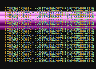
Here’s a similar DLI to the above, except it changes the luminance value instead of the color value to make the effect easier to see. It starts with a bright pink and gets dimmer down to a dark red after 32 scan lines. But this time, the display list has two mode 4 lines that have the DLI bit set, the 2nd and 4th:
dlist   .byte $70,$70,$70
        .byte $44,$00,$40
        .byte $84  ; first DLI triggered on last scan line
        .byte 4
        .byte $84  ; second DLI triggered on last scan line
        .byte 4,4,4,4,4,4,4,4
        .byte 4,4,4,4,4,4,4,4
        .byte 4,4,4,4
        .byte $41,<dlist,>dlist
The first DLI takes 32 scan lines to complete, but it is only 16 scan lines through its operation when the second DLI hits:
- Source Code: dli_interrupting_dli.s
- Executable: dli_interrupting_dli.xex
When a DLI is interrupted, its state is saved just as if a normal program was interrupted. The interrupting code is then executed, and upon its completion, the control returns to the DLI at the point where it left off. But at this point, due to the interrupting event, the restored DLI will be resumed some number of scan lines below where it was interrupted, likely resulting in unplanned behavior.
dli     pha             ; save A & X registers to stack
        txa
        pha
        ldx #16         ; make 16 color changes
        lda #$5f        ; initial bright pink color
        sta WSYNC       ; first WSYNC gets us to start of scan line we want
?loop   sta COLBK       ; change background color
        sec
        sbc #1          ; make dimmer by decrementing luminance value
        dex             ; update iteration count
        sta WSYNC       ; make it the color change last ...
        sta WSYNC       ;   for two scan lines
        bne ?loop       ; sta doesn't affect processor flags so we are still    checking result of dex
        lda #$00        ; reset background color to black
        sta COLBK
        pla             ; restore X & A registers from stack
        tax
        pla
        rti             ; always end DLI with RTI!
Because the display list vector VDLSTL is not changed, the same code will
be called each time an interrupt occurs.
The first DLI hits and starts with a bright background color on the first scan
line of the third line of text. But because this display list takes a long
time, the second DLI on the 4th text line gets triggered before the first DLI
has hit its RTI instruction. ANTIC interrupts the first DLI and starts the
2nd DLI anyway. This effect is visible in the 5th line of text: the background
color is bright again.
But notice another artifact: the effect on the 5th line of text isn’t on its first scan line, but its second:
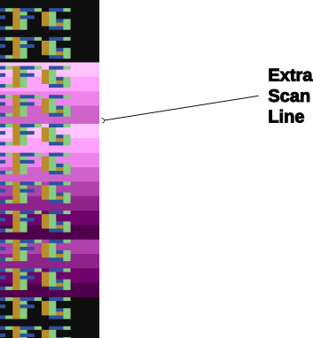
This is due to the fact that a WSYNC was called on the previous scan line, but
the interrupt happened as well. The interrupt takes some cycles to begin, and
by the time that happened and ANTIC stole all of its cycles to set up the
text mode line, there weren’t enough cycles left for the first WSYNC in the
DLI code to happen on the same scan line. This forces that WSYNC to happen
on the next line, causing the delay and the appearance of a 3rd scan line of the
same color before the second DLI starts its color cycling.
The second DLI completes and performs its RTI, but then it returns control
to the first DLI, which is already halfway done with its color cycling. When it
resumes control, it is in 9th line of text on the screen, so it has four more
color changes before it hits its own RTI.
Emulator Differences
The DLI interrupting another DLI is clearly an edge case, and edge cases are always good stress tests for emulators. A difference is clearly visible below when comparing a zoomed in portion of the display generated by the Altirra emulator as compared to the atari800 emulator (standalone or as embedded in Omnivore, they are the same code and produce the same result):
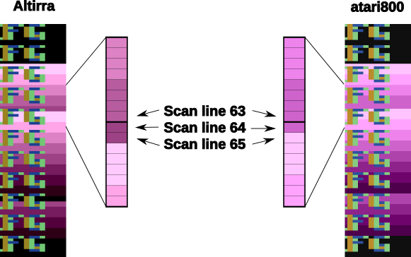
Notice how Altirra gets the color from the first DLI for two scan lines, 64
and 65, before the correct color appears on scan line 66. The output from
Altirra shows that the NMI doesn’t happen until between scan line 63 and 64.
But clearly, the sta COLBK at scan line 63 is taking effect on scan line
64, because scan line 64 has the background color $57. It appears the
store of $5f on scan line 65, started on cycle 1 of that line, isn’t
actually executed until much, much later since the sec doesn’t begin until
cycle 108. This puts that color change in the horizontal blank period of scan
line 65, which would seem to explain why Altirra shows two scan lines with the
background color from the first DLI.
This is the CPU history from the Altirra emulator:
   60:  3 | A=58 X=09 Y=00 (   I C) | 3030: 8D 0A D4          STA WSYNC
   60:  7 | A=58 X=09 Y=00 (   I C) | 3033: 8D 0A D4          STA WSYNC
   60:108 | A=58 X=09 Y=00 (   I C) | 3036: D0 F1             BNE $3029
   61:107 | A=58 X=09 Y=00 (   I C) | 3029: 8D 1A D0  L3029   STA COLBK
   61:111 | A=58 X=09 Y=00 (   I C) | 302C: 38                SEC
   61:113 | A=58 X=09 Y=00 (   I C) | 302D: E9 01             SBC #$01
   62:  1 | A=57 X=09 Y=00 (   I C) | 302F: CA                DEX
   62:  3 | A=57 X=08 Y=00 (   I C) | 3030: 8D 0A D4          STA WSYNC
   62:  7 | A=57 X=08 Y=00 (   I C) | 3033: 8D 0A D4          STA WSYNC
   62:108 | A=57 X=08 Y=00 (   I C) | 3036: D0 F1             BNE $3029
   63:107 | A=57 X=08 Y=00 (   I C) | 3029: 8D 1A D0  L3029   STA COLBK
- NMI interrupt (DLI)
   64:  5 | A=57 X=08 Y=00 (   I C) | E791: 2C 0F D4  LE791   BIT NMIST
   64: 11 | A=57 X=08 Y=00 (N  I C) | E794: 10 03             BPL $E799
   64: 13 | A=57 X=08 Y=00 (N  I C) | E796: 6C 00 02          JMP (VDSLST)
   64: 19 | A=57 X=08 Y=00 (N  I C) | 301F: 48                PHA
   64:102 | A=57 X=08 Y=00 (N  I C) | 3020: 8A                TXA
   64:104 | A=08 X=08 Y=00 (   I C) | 3021: 48                PHA
   64:107 | A=08 X=08 Y=00 (   I C) | 3022: A2 10             LDX #$10
   64:109 | A=08 X=10 Y=00 (   I C) | 3024: A9 5F             LDA #$5F
   64:111 | A=5F X=10 Y=00 (   I C) | 3026: 8D 0A D4          STA WSYNC
   65:  1 | A=5F X=10 Y=00 (   I C) | 3029: 8D 1A D0  L3029   STA COLBK
   65:108 | A=5F X=10 Y=00 (   I C) | 302C: 38                SEC
   65:110 | A=5F X=10 Y=00 (   I C) | 302D: E9 01             SBC #$01
   65:112 | A=5E X=10 Y=00 (   I C) | 302F: CA                DEX
   66:  0 | A=5E X=0F Y=00 (   I C) | 3030: 8D 0A D4          STA WSYNC
   66:  4 | A=5E X=0F Y=00 (   I C) | 3033: 8D 0A D4          STA WSYNC
   66:108 | A=5E X=0F Y=00 (   I C) | 3036: D0 F1             BNE $3029
   67:107 | A=5E X=0F Y=00 (   I C) | 3029: 8D 1A D0  L3029   STA COLBK
The atari800 emulator hits the DLI two instructions earlier than Altirra,
immediately after the two sta WSYNC commands (and therefore before the
sta COLBK that causes Altirra to have a new color on scan line 64). In the
atari800/Omnivore instruction history below:
60   5 | 58 09 25 ---I-C f6 3336  8d 0a d4  sta WSYNC     $d40a=58 (was d0)
60 106 | 58 09 25 ---I-C f6 3339  8d 0a d4  sta WSYNC     $d40a=58 (was d0)
61 106 | 58 09 25 ---I-C f6 333c  d0 f1     bne $332f     (taken)
61 109 | 58 09 25 ---I-C f6 332f  8d 1a d0  sta COLBK     $d01a=58 (was 0f)
61 113 | 58 09 25 ---I-C f6 3332  38        sec
62   1 | 58 09 25 ---I-C f6 3333  e9 01     sbc #$01      A=57
62   3 | 57 09 25 ---I-C f6 3335  ca        dex           X=08
62   5 | 57 08 25 ---I-C f6 3336  8d 0a d4  sta WSYNC     $d40a=57 (was d0)
62 106 | 57 08 25 ---I-C f6 3339  8d 0a d4  sta WSYNC     $d40a=57 (was d0)
63   0 | --DLI
63 106 | 57 08 25 ---I-C f3 c018  2c 0f d4  bit NMIRES    $d40f=1c N=1
63 110 | 57 08 25 N--I-C f3 c01b  10 03     bpl $c020     (not taken)
63 112 | 57 08 25 N--I-C f3 c01d  6c 00 02  jmp (VDSLST)  ($0200)=$3325
64   4 | 57 08 25 N--I-C f3 3325  48        pha           $01f3=57
64   7 | 57 08 25 N--I-C f2 3326  8a        txa           A=08 N=0
64   9 | 08 08 25 ---I-C f2 3327  48        pha           $01f2=08
64  12 | 08 08 25 ---I-C f1 3328  a2 10     ldx #$10      X=10
64  14 | 08 10 25 ---I-C f1 332a  a9 5f     lda #$5f      A=5f
64  16 | 5f 10 25 ---I-C f1 332c  8d 0a d4  sta WSYNC     $d40a=5f (was d0)
64 107 | 5f 10 25 ---I-C f1 332f  8d 1a d0  sta COLBK     $d01a=5f (was 0f)
64 111 | 5f 10 25 ---I-C f1 3332  38        sec
64 113 | 5f 10 25 ---I-C f1 3333  e9 01     sbc #$01      A=5e
65   1 | 5e 10 25 ---I-C f1 3335  ca        dex           X=0f
65   3 | 5e 0f 25 ---I-C f1 3336  8d 0a d4  sta WSYNC     $d40a=5e (was d0)
65 106 | 5e 0f 25 ---I-C f1 3339  8d 0a d4  sta WSYNC     $d40a=5e (was d0)
66 106 | 5e 0f 25 ---I-C f1 333c  d0 f1     bne $332f     (taken)
66 109 | 5e 0f 25 ---I-C f1 332f  8d 1a d0  sta COLBK     $d01a=5e (was 0f)
the DLI starts late on scan line 63 as (naively) expected and gets to the
sta WSYNC early in scan line 64 while there is still time to hit the sta
COLBK while still on scan line 64. This changes scan line 65 to be the
correct background color for the second DLI.
Note
I’m not sure what’s going on with the differences in the WSYNC behavior between the two emulators. On Altirra, the two WSYNC commands seem to occur on scan line 62, but their effects aren’t felt immediately, so perhaps this is what’s causing the DLI to hit on scan line 64 instead of scan line 63. On atari800, the WSYNC commands cause their effects to be felt immediately, in the next command. I would presume that Altirra is closer to what’s going on with real hardware, as the author of Altirra has written the definitive guide to the internals of the machine, and Altirra has always been the leader in cycle-exact emulation.
I think the takeaway from this section is: don’t let your DLI get interrupted by anything else, or it is likely that you will encounter emulation differences.
VBI Interrupting A DLI
Here is an example of the vertical blank interrupting a DLI.

- Source Code: vbi_interrupting_dli.s
- Executable: vbi_interrupting_dli.xex
The DLI is started at the bottom of the screen, gets interrupted by the VBI,
and picks up again when VBI ends. Even though the electron beam is turned off,
WSYNC is still called and performs its delay function when the scan line
is off screen. The resulting image resumes its color cycling background on the
top of the screen, stopping after 128 scan lines even though only a fraction
of those are actually visible on screen.
DLI Interrupting A VLI
And for completeness, here is an example of a DLI interrupting the vertical blank.

- Source Code: dli_interrupting_vbi.s
- Executable: dli_interrupting_vbi.xex
The vertical blank routine would have to be quite long and the DLI set very early in the display list before this would happen.
Note
In my own game development, I have run into this effect happening intermittently, where occasionally the VBI runs very long due to some complicated game logic that happens only under certain conditions. It’s something to be aware of.
In this example, this DLI is set on the final blank line of the display list, so the display list begins with these bytes:
.byte $70,$70,$f0
triggering the DLI on scan line 24. The vertical blank has run from scan lines 248 through 262 on one frame, and through 23 scan lines of the following frame before getting interrupted by the DLI.
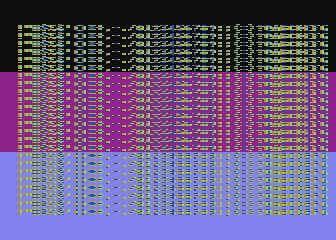
To visualize the processing in the vertical blank, this example changes background color as fast as it can once the vertical blank starts, up to the 100th scan line of the generated image. It gets interrupted on scan line 23 for the DLI.
The DLI is one we’ve seen before, just changing background color with
WSYNC. Once it has completed, it returns and the VBI routine picks up where
it left off, changing background color as fast as it can.
DLI on the JVB Instruction
A DLI on the JVB instruction at the end of the display list is possible, but has an interesting property: it triggers DLIs on every scan line until the vertical blank.
If your DLI is not short enough, it will keep getting interrupted by the DLI on triggered by the next scan line, stacking up interrupts until mercifully the triggering process is stopped by the vertical blank after 248 scan lines have been generated.
Note
As each new frame is generated in an emulator, it will enumerate the scan lines starting from zero. There are 248 scan lines before the vertical blank, which will be displayed as scan lines 0 - 247. The scan line labeled 248 will be the first scan line of the vertical blank.
After the vertical blank routine exits, the stacked-up DLI calls will have to
unwind themselves so the most recently interrupted DLI (from scan line 247,
the scan line just before the vertical blank) will resume and execute code
until its RTI. This will pop data off the stack and return control to the
DLI that was interrupted on scan line 246, and so-forth until all the
interrupted DLIs have issued their RTI instructions.
On a standard length display list that generates 24 blank lines followed by 192 output lines, the JVB instruction will be on scan line 224. Since the JVB technically generates a single blank line in the display list, the DLI will also be triggered on scan line 224. This case would produce 24 DLIs before the vertical blank.
DLIs in a Nutshell
DLIs provide you with a way to notify your program at a particular vertical location on the screen. They pause (or interrupt) the normal flow of program code, save the state of the machine, call your DLI subroutine, and restore the state of the computer before returning control to the code that was interrupted.
Warning
Here are the requirements for successful use of DLIs:
your DLI routine must save any registers it clobbers
restore any registers you save before exiting
exit with an
RTIuse
WSYNCif necessarybe aware of cycles stolen by ANTIC: you could have only 60 cycles per scan line in higher resolution graphics modes, and as few as 10 (!) on the first line of text modes
store the address of your routine in
VDSLSTbefore enabling DLIs withNMIENguard against the DLI itself being interrupted
Note that nowhere in that list was the requirement that the DLI be short. It doesn’t have to be, and in fact DLIs that span multiple scan lines are similar to kernels used in Atari 2600 programming. The difference is that ANTIC steals cycles depending on a bunch of factors, so the total cycle counting approach (or Racing the Beam) is usually not possible.
However, most DLIs that you will run across in the wild are short, because they typically don’t do a lot of calculations. Most of the setup work will generally be done outside of the DLI and the DLI itself just handles the result of that work.
![]()
Advanced DLI Examples
The following examples are available in both source code form and as XEX files at the dli_tutorial source code repository on github.
They are coded using MAC/65 assembler syntax, but very few assembler-specific features are actually used, so they should be trivially ported to other assemblers.
To get a copy of all the examples and source code, you can download and install git for your platform. Then open a command line prompt on your computer and enter the command:
git clone https://github.com/playermissile/dli_tutorial.git
to download the complete repository.
You can also download individual assembly source and XEX files from links in each section.
In an attempt to de-clutter the examples as much as possible, most of the
boilerplate code (for initialization and setup tasks) has been placed in
libraries that are included during the compilation process. These are files
like util.s, util_dli.s and so forth, and are available in the source code repository or directly here.
Topic #1: DLI Positioning
The following examples deal with various techniques regarding placing the DLI on screen.
#1.1: Multiple DLIs
- Source Code: multiple_dli_same_page.s
- Executable: multiple_dli_same_page.xex
One of the problems with having a single DLI vector is: what do you do when you want to have more than one DLI?
Some techniques that you will see in the wild:
use
VCOUNTto check where you are on screen and branch accordinglyincrement an index value and use that to determine which DLI has been called
change the
VDLSTLvector to point to the next DLI in the chain
Here’s an optimization of the last technique that can save some valuable cycles: put your DLIs in the same page of memory and only change the low byte.
*= (* & $ff00) + 256 ; next page boundary
dli pha ; only using A register, so save it to the stack
lda #$55 ; new background color
sta WSYNC ; first WSYNC gets us to start of scan line we want
sta COLBK ; change background color
lda #<dli2 ; point to second DLI
sta VDSLST
pla ; restore A register from stack
rti ; always end DLI with RTI!
dli2 pha ; only using A register, so save it to the stack
lda #$88 ; new background color
sta WSYNC ; first WSYNC gets us to start of scan line we want
sta COLBK ; change background color
pla ; restore A register from stack
rti ; always end DLI with RTI!
vbi lda #<dli ; set DLI pointer to first in chain
sta VDSLST
lda #>dli
sta VDSLST+1
jmp XITVBV ; always exit deferred VBI with jump here
This is a simplistic example, but keeping the high byte constant inside the
DLI saves 6 cycles (by obviating the need for changing the high byte with
LDA #>dli2; STA VDLSTL+1). That may be enough for this optimization to be
useful.
#1.2: Moving the DLI Up and Down the Screen
The DLI subroutine itself doesn’t directly know what scan line caused the
interrupt because all DLIs are routed through the same vector at VDLSTL.
The only trigger is in the display list: the DLI bit on the display list
instruction.
- Source Code: moving_dli.s
- Executable: moving_dli.xex
The display list can be modified in place to move the DLI to different lines without changing any DLI code. The code to move the DLI should be performed in the vertical blank to prevent the display list from being modified as ANTIC is using it to create the display:
move_dli_line
        ldx last_dli_line ; get line number on screen of old DLI
        lda dlist_line_lookup,x ; get offset into display list of that line number
        tax
        lda dlist_first,x ; remove DLI bit
        and #$7f
        sta dlist_first,x
        ldx dli_line    ; get line number on screen of new DLI
        stx last_dli_line ; remember
        lda dlist_line_lookup,x ; get offset into display list of that line number
        tax
        lda dlist_first,x ; set DLI bit
        ora #$80
        sta dlist_first,x
        rts
The example allows the display list to be set on blank lines at the top of the display, and on the last mode 4 line in the display list which displays the background below the last mode 4 line on the screen.
Topic #2: Colors
We have already seen several examples of using DLIs to show more colors on screen. The following examples are included to address more topics in common use in games or title screens.
#2.1: Marching Rainbow Text
Using code almost identical to the rainbow effect, a common effect seen in title screens can be created:
- Source Code: marching_rainbow.s
- Executable: marching_rainbow.xex
Using a simple display list:
dlist   .byte $70,$70,$70,$70,$70,$70  ; 48 blank lines
        .byte $46,<text,>text ; Mode 6 + LMS, setting screen memory to text
        .byte 6            ; Mode 6
        .byte $70,$70      ; 16 blank lines
        .byte 7,7,7        ; 3 lines of Mode 7
        .byte $70          ; 8 blank lines
        .byte $f0          ; 8 blank lines + DLI on last scan line
        .byte 7,7          ; 2 lines of Mode 7
        .byte $41,<dlist,>dlist ; JVB, restart same display list on next frame
the DLI simply loads the start_color variable as the initial color each
time it is called, then increments the value stored in the hardware color
register for playfield color zero (COLPF0) as it makes WSYNC calls to
advance one scan line down the screen. Each scan line increases luminance (i.e.
gets brighter), until the low 4 bits controlling the luminance overflows into
the high 4 bits, changing the color to the next in the Atari’s color palette at
zero luminance.
dli     pha             ; save A & X registers to stack
        txa
        pha
        ldx #32         ; make 32 color changes
        lda start_color ; initial color
        sta WSYNC       ; first WSYNC gets us to start of scan line we want
?loop   sta COLPF0      ; change text color for UPPERCASE characters in gr2
        clc
        adc #$1         ; change color value, making brighter
        dex             ; update iteration count
        sta WSYNC       ; sta doesn't affect processor flags
        bne ?loop       ; we are still checking result of dex
        lda #text_color ; reset text color to normal color
        sta COLPF0
        dec start_color ; change starting color for next time
        pla             ; restore X & A registers from stack
        tax
        pla
        rti             ; always end DLI with RTI!
At the end of the DLI, start_color is decremented, meaning that the next
time the DLI is called it will start with one luminance value lower than it did
last time. This gives the appearance of the previous rainbow of color being
“pushed” down the screen and a new darker line being inserted at the top of the
rainbow.
Changing that dec start_color to inc start_color would have the
opposite effect and the rainbow of color would appear to move upward.
Alternatively, leaving the dec start_color but changing the clc, adc
#$1 to:
sec
sbc #$1         ; change color value, making darker
would have the same effect as inc start_color.
Topic #3: Character Sets
The character set on the Atari is comprised of 128 glyphs, each of which is 8 bytes in size for a total of 1024 bytes for a complete font. The characters are defined in ANTIC font order, not ATASCII order, so the first 64 characters are the ATASCII characters 32 - 95 (symbols, numbers, and upper case letters), the next 32 are the graphic symbols on the control characters, and the final 32 are the lower case letters and a few remaining graphic symbols.
See also
More resources about character sets are available:
CHBASin Mapping the AtariCHBASEin Mapping the Atari
#3.1: Changing Character Sets
An extremely simple DLI is all that’s needed to change the character set at a particular scan line.
- Source Code: simple_chbase.s
- Executable: simple_chbase.xex
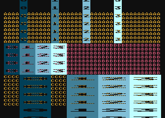
This example uses two character sets: the default character set at the top of
the screen, and an character set designed for ANTIC 4 for the bottom. The
screen is broken up into 3 bands, one set of 8 lines of ANTIC mode 2 and two
sets each containing 8 lines of ANTIC mode 4. The top two bands have the normal
character set (CHBASE = $e000) and the bottom band has a custom character
set designed for the 5 color mode.
The DLI is set on the 16th text line: the final line in the second band of 8 lines so that the character set change affects the 3rd band of 8 lines:
; mixed mode 2 and mode 4 display list
dlist_static
        .byte $70,$70,$70
        .byte $42,$00,$80
        .byte 2,2,2,2,2,2,2     ; first band has 8 lines of mode 2
        .byte 4,4,4,4,4,4,4,$84 ; 2nd band: 8 lines of mode 4 + DLI on last line
        .byte 4,4,4,4,4,4,4,4   ; 3rd band: 8 lines of mode 4
        .byte $41,<dlist_static,>dlist_static
The font for the top of the screen is set during the init routine using the
the shadow register CHBAS, not the hardware register CHBASE. It will be
reloaded every vertical blank by the operating system:
lda #$e0
sta CHBAS
The DLI is very simple, just loading the new character set, but this time using
the hardware register CHBASE:
dli     pha             ; only using A register, so save it to the stack
        lda #>font_data ; page number of new font data
        sta WSYNC       ; first WSYNC gets us to start of scan line we want
        sta CHBASE      ; store to hardware register to affect change immediately
        pla             ; restore A register from stack
        rti             ; always end DLI with RTI!
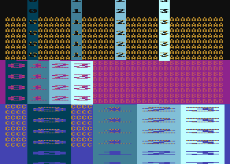
#3.x: Multiple Interleaved Character Sets for Soft Sprites
The author of the cc65 DLI tutorial, Yaron Nir, started a recent topic on AtariAge that described a technique to use a DLI to change the character set on each line to facilitate the use of soft sprites.
Soft sprites require shifting images within characters to achieve smooth motion, so the height of the soft sprites determines how many lines of characters needed, and the width in pixels as compared to the width of each character determines the number of characters must be placed horizontally. ANTIC mode 4 is 8 scan lines tall and has 4 pixels across. Vertically, you could have sprites of height 9 scan lines using 2 character sets, 17 scan lines with 3 character sets, 25 scan lines with 4 character sets, etc. Sprites would need 2 characters side-by-side for up to 5 pixels, 3 characters for 9 pixels, 4 characters for 13 pixels. etc.
<image here>
With only 128 glyphs per character set, bit patterns are at a premium. If, say, 64 characters are used for background, only 64 characters remain for sprites. Using a 4x3 grid for sprites takes 12 out of the 64 available sprite glyphs, so 5 (independent) soft sprites would be available since that would use 60 characters. Limiting directions can reduce that number; if your sprites move only horizontally, for instance, sprites of 13 pixels by 16 scan lines would only take a 3x2 grid, or only 6 characters.
The advantage of using a DLI with multiple character sets is that more characters are available for sprites.
Topic #4: Player/Missile Graphics
Player/Missile Graphics is the sprite system provided by the GTIA: independently positioned overlays on the playfield graphics that don’t disturb the playfield.
Note
the word sprite in this sense wasn’t in use when the Atari was designed, and several sources claim that it was coined by the designers of the Texas Instruments TI 9918 graphics chip at about the same timeframe.
The GTIA provides 4 players with independent colors (from each other or the playfield) and 4 missiles with colors matching their respective player, or the 4 missiles can be combined into a 5th player with its own color (although this reuses one playfield color). The players are 8 bits wide and can be displayed as one, two, or four color clocks wide per bit. This corresponds a width on screen of 8, 16, and 32 color clocks, respectively. Widths for all players and missiles can be set independently.
Each player and missile can be positioned at an arbitrary horizontal location by setting a hardware register, but vertical positioning requires copying data to particular locations in the memory area reserved for it. Each player spans the height of the screen, and it is only the bit pattern in its storage area that determines what is drawn on a particular scan line.
Missiles are two bits wide each with all 4 missiles packed into a single byte for a particular scan line. Bit masking is required to set data for one missile without affecting the others.
The quick summary for our purposes is that horizontal repositioning of players is fast, it takes only a single store instruction. Vertical repositioning of player image data is slow, it requires copying memory around.
#4.1: Multiplexing Players Vertically
Reusing players (multiplexing) vertically is straightforward, meaning that a single player can be used to display arbitrary images at different vertical locations on the screen, provided that there is no vertical overlap.
- Source Code: simple_multiplex_player.s
- Executable: simple_multiplex_player.xex
Using the hardware HPOSPn or HPOSMn registers, the DLI will
immediately change where ANTIC will draw the player or missile. The next time
ANTIC draws the player on a scan line, it will use this new position.
in the appropriate player or missile X position register. This demo uses the page-alignment trick for the second DLI, and changes the position and size of the players at each interrupt.
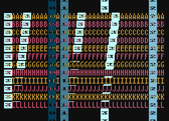
This demo splits the screen vertically into 3 horizontal bands, A, B & C, with
the players extending the full height of the screen and labeled 0 through 3.
This example uses the VBI to set the players for band A, the dli routine
is the bottom of band A (and the top of band B) and therefore sets the players
for band B, and the dli2 routine is the bottom of band B (and the top of
band C) and controls the players for band C.
vbi     lda #<dli       ; set DLI pointer to first in chain
        sta VDSLST
        lda #>dli
        sta VDSLST+1
        lda #$40        ; set player positions and sizes ...
        sta HPOSP0      ;   for the top of the screen
        lda #$60
        sta HPOSP1
        lda #$80
        sta HPOSP2
        lda #$a0
        sta HPOSP3
        lda #0
        sta SIZEP0
        sta SIZEP1
        sta SIZEP2
        sta SIZEP3
        jmp XITVBV      ; always exit deferred VBI with jump here

        *= (* & $ff00) + 256 ; next page boundary

dli     pha             ; only using A register, so save it to the stack
        lda #$55        ; new background color
        sta WSYNC       ; first WSYNC gets us to start of scan line we want
        sta COLBK       ; change background color
        lda #$30        ; change position and sizes of players
        sta HPOSP0
        lda #$40
        sta HPOSP1
        lda #$50
        sta HPOSP2
        lda #$60
        sta HPOSP3
        lda #1
        sta SIZEP0
        sta SIZEP1
        sta SIZEP2
        sta SIZEP3
        lda #<dli2      ; point to second DLI
        sta VDSLST
        pla             ; restore A register from stack
        rti             ; always end DLI with RTI!

dli2    pha             ; only using A register, so save it to the stack
        lda #$84        ; new background color
        sta WSYNC       ; first WSYNC gets us to start of scan line we want
        sta COLBK       ; change background color
        lda #$40        ; change position and sizes of players
        sta HPOSP0
        lda #$70
        sta HPOSP1
        lda #$90
        sta HPOSP2
        lda #$b0
        sta HPOSP3
        lda #3
        sta SIZEP0
        sta SIZEP1
        sta SIZEP2
        sta SIZEP3
        pla             ; restore A register from stack
        rti             ; always end DLI with RTI!
In discussing the timing issues that cause errors at the band boundaries, the players in band A are positioned by the VBI, and so are in place from well off the top of the screen and are correctly positioned at the first scan line. Players 0, 1, and 2 are correct at the bottom of the band, but player 3 extends one scan line too far, into band B.
The top of band B shows both position and size errors. When the first DLI hits
on the last scan line of the 6th line of text, the background color is changed
at the WSYNC and ANTIC moves on to start drawing the first scan line of
the 7th line of text (which is the first line of text in band B.) Players 0,
1, and 2 are positioned correctly, which means their horizontal positions were
set before ANTIC reached that portion of the scan line. The 3rd player remains
in the same position as it was in band A, meaning that its horizontal position
wasn’t set in time. ANTIC had stolen enough cycles setting up the mode 4 font
that the 6502 didn’t get a chance to process the sta HPOS3 before ANTIC
had to draw that portion of the scan line. Since the code sets sizes after the
horizontal positions, none of the sizes are set until the 2nd scan line of
band B.
The transition to band C with the dli2 routine produces similar results,
there just isn’t enough time with the WSYNC used for the color change
and all the cycles stolen by ANTIC mode 4 to process the all of the player
changes in the first scan line of the band. Players 0, 1, and 2 are moved,
player 3 is not, and all 4 players don’t get the correct size until the 2nd
scan line of the band.
It’s possible to imagine a scenario where a scan line of a player is not
visible at all. For example, if player 3 above had been positioned very far to
the right and HPOSP3 was changed to move player 3 to the far left side, it
could be possible that ANTIC has already drawn the left side of the screen but
hadn’t yet reached the right side where player 3 had been positioned. Because
HPOSP3 is now showing that player 3 is on the left side of the screen,
ANTIC would not draw it at its old location on the right side of the screen.
It’s also possible, with careful timing, to reuse a player on a single line. However, purposeful use of this would difficult given all the different horizontal locations of ANTIC’s cycle stealing.
Mode 4 was chosen (in all of its cycle-stealing glory) for these examples to
get an idea of the worst-case scenerio. Taking out the WSYNC and the color
change did allow enough time that both the positions and sizes were changed
without visible artifacts:
but this is very simple code and the more real-world example in the next section will show that a buffer zone of several scan lines is necessary to make sure a player isn’t split across a band boundary or, as described above, even duplicating a line of the player or missing a scan line.
#4.2: Multiplexing With Horizontal Motion
Increasing the number of bands and adding independent player movement within each band requires some data structures and a DLI to control placement in each band.
- Source Code: multiplex_player_movement.s
- Executable: multiplex_player_movement.xex
The approach used in this example is to use a single DLI that uses an index value to determine which band it is operating within. This index value is used as an offset into arrays that hold the sprite X position, size, color, etc.
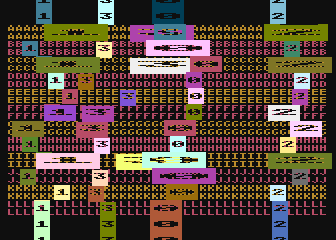
There are a lot of independently moving objects in this demo: 12 bands, each with 4 players. There are very obvious timing issues in most bands on the first scan line after the DLI as sometimes the hardware registers for a player hasn’t been updated fully until the second scan line.
; same DLI routine is used for each band, the band_dli_index is used to set
; player information for the appropriate band
dli_band
        pha             ; using A & X
        txa
        pha
        inc band_dli_index ; increment band index, VBI initialized to $ff,
        ldx band_dli_index ;   so will become 0 for band A

        ; control band X positions of players
        lda bandp0_x,x  ; x position of player 0 in this band
        sta HPOSP0
        lda bandp0_color,x ; color of player 0 for this band
        sta COLPM0
        lda bandp0_size,x ; size of player 0 for this band
        sta SIZEP0

        lda bandp1_x,x  ; as above, but for players 1 - 3
        sta HPOSP1
        lda bandp1_color,x
        sta COLPM1
        lda bandp1_size,x
        sta SIZEP1

        lda bandp2_x,x
        sta HPOSP2
        lda bandp2_color,x
        sta COLPM2
        lda bandp2_size,x
        sta SIZEP2

        lda bandp3_x,x
        sta HPOSP3
        lda bandp3_color,x
        sta COLPM3
        lda bandp3_size,x
        sta SIZEP3

?done   pla             ; restore A & X
        tax
        pla
        rti             ; always end DLI with RTI!
The addreses bandpN_x, bandpN_color, and bandpN_size (where N is
the player number) are declared as lists with the number of entries equal to
the number of bands. band_dli_index is incremented each time the DLI
starts, and uses that index into the lists so it places the players in the
correct location for that band.
Notice that is all the DLI does. It does not calculate movement or perform any player logic, it simply puts players on the screen in the appropriate place for that band. All the calculation is done in the vertical blank:
; calculate new positions of players in all bands
vbi     ldx #0
?move   lda bandp0_x,x  ; update X coordinate
        clc             ;   by adding velocity.
        adc bandp0_dx,x ;   Note that velocity of $ff
        sta bandp0_x,x  ;   is same as -1
        cmp #$30        ; check left edge
        bcs ?right      ; if >=, it is still in playfield
        lda #1          ; nope, <, so make velocity positive
        sta bandp0_dx,x
        bne ?cont
?right  cmp #$c0        ; check right edge
        bcc ?cont       ; if <, it is still in playfield
        lda #$ff        ; nope, >=, so make velocity negative
        sta bandp0_dx,x
?cont   inx             ; next player
        cpx #num_dli_bands * 4 ; loop through 12 bands * 4 players each
        bcc ?move

        lda #$ff        ; initialize band index to get ready for band A
        sta band_dli_index
        jmp XITVBV      ; always exit deferred VBI with jump here
Unlike the simple multiplexing demo in the previous section, this VBI does not
set any positions of players. Instead, this demo sets the DLI bit on the last
group of 8 blank lines at the beginning of the display list, before any mode 4
lines. This initial DLI will set the players for band A, and as you can see in
the demo the players above band A use the same X position and size as band L.
The colors are not the same as band L, however, because of the use of the
shadow registers to set the initial color in the init_pmg subroutine.
#4.3: Reusing Players Horizontally
Reusing players on the same scan line is possible, but requires cycle counting and has limitations, especially in text modes. The complicated cycle stealing performed by ANTIC will require consulting timing reference charts (such as in the Altirra Hardware Reference Manual) to determine how well it can be used for a particular graphics mode.
- Source Code: reusing_player_horz.s
- Executable: reusing_player_horz.xex
Here’s the DLI that produces the effect above, where player 3 has multiple copies at the same vertical position. Again there are 12 vertical bands (this time ANTIC mode 5), where the first copy of player 3 is at the left side of the screen and the other 3 shift slowly to the left as it moves down bands in order to find the minimum possible horizontal shift between copies. This is not a kernel (see the next section for that), so the DLI bit is set on each of the mode 5 lines.
dli     pha             ; using A & X
        txa
        pha

        dec copy1       ; move copies to the left one color clock each band
        dec copy2
        sta WSYNC       ; skip rest of last line of DLI line
        dec copy3       ; not enough time to do all 3 decrements before 1st WSYNC
        ldx #14         ; prepare for 14 scan lines in the loop
        sta WSYNC       ; skip 1st line of mode 5 where ANTIC steals almost all cycles
?loop   lda #48         ; set initial position of player 3
        sta HPOSP3
        nop             ; we're still on the tail end of the prevous scan
        nop             ;   line, so we need to wait until the electron beam
        nop             ;   passes this first position before we set the
        nop             ;   next HPOS.
        nop
        nop
        lda copy1       ; can't place copies until after electron beam draws
        sta HPOSP3      ;   the player in the previous location. If you try
        lda copy2       ;   to move HPOSP3 too early, the previous location
        sta HPOSP3      ;   won't even get drawn. Too late, and it won't draw
        lda copy3       ;   anything in the current location.  It's a battle.
        sta HPOSP3
        dex
        beq ?done
        sta WSYNC
        bne ?loop

?done   pla             ; restore A & X
        tax
        pla
        rti             ; always end DLI with RTI!
This requires a VBI to reset the starting horizontal position at the top of each frame.
vbi     lda #68         ; reset position counters for each copy of player 3
        sta copy1
        lda #122
        sta copy2
        lda #156
        sta copy3
        jmp XITVBV      ; always exit deferred VBI with jump here
There is a lot to unpack here.
First: using a text mode is a mistake because ANTIC steals so many cycles on
the first scan line that there’s no way to place copies on that scan line. On
subsequent lines, there is enough time to make multiple copies of a player
except for the last line that will have to contain the RTI instruction.
However, because this is not using a kernel- style DLI where it takes control
for all 192 lines, the RTI has to happen before the last scan line so
there is enough time for the interrupt processing for the next DLI without the
the current DLI getting interrupted, which would then stack interrupts and
cause scan line offsets.
Second: notice the bands places in which the number 3 isn’t drawn in the player, instead only a single scan line in the player 3 color appears. This means there are not enough available cycles to set the new position of the player before the electron beam has already passed the desired horizontal position.
The takeaways here:
the cycle counting necessary will be much easier using bitmap modes
it will probably be more successful to use a kernel rather than multiple DLIs
the author may revisit this technique at some point, but for now will leave further exploration to the reader, assuming the reader is much more patient regarding cycle counting than the author.
#4.x: Multiplexing with Arbitrary Motion
Vertical movement within bands requires the moving memory around the
player/missile graphics area (pointed to by PMBASE) as in normal usage,
with the following limitations:
players must stay within their assigned band, otherwise they will get split across bands when the DLI occurs.
players should avoid the first few scan lines below the top of the band boundary to prevent splitting
when moving a player vertically within a band, only erase data from that band to prevent affecting the multiplexed players in other bands
<example goes here>
#4.x: Multiplexing With Collision Detection
If it is important to tell in which band a has collided occurred, the DLI that starts a new band will be required to save the collision status registers, which will determine if a collision happened in the previous band. It will then reset the collision registers so the following DLI can check what happened in this band.
If the knowledge of the band is not important, you can just check the collision registers in the vertical blank, which will report if there have been any collisions with anything in any band.
<example goes here>
Topic #5: Kernels
The concept of a kernel comes from Atari 2600 programming. The 2600 does not have enough memory to store an entire frame – it has a line buffer, rather than a frame buffer. To create a graphic image with any vertical detail, the code must build the screen line-by-line, changing graphic information as the electron beam moves down the screen.
Kernels for our purposes will be DLIs that take control for many scan lines to
perform graphic operations that are not possible otherwise. We have seen
horizontal positioning of players accomplished with a traditional DLI setup
with interrupts on multiple display list commands. It could have been
performed using a kernel, which (assuming the graphics mode is bitmapped
rather than text) would have removed the restriction created by need for extra
cycles near the RTI instruction.
Kernels are a very advanced topic. The Atari 8-bit computers are the direct successor to the 2600, and the ANTIC and GTIA were designed to automate common tasks that in the 2600 requires kernel programming. Because so much is possible without kernels, this tutorial is not going to spend much time with this topic. However, a few examples are presented here to give you an idea of how they work.
#5.1: Background Color Change Within Scan Line
A simple kernel can be used to change the background color to “split” the screen horizontally. Having learned a lesson or two, the author is using a graphics mode for the following example, mode E (the 160x192, 4 color mode):

- Source Code: background_color_kernel.s
- Executable: background_color_kernel.xex
which does show much more (but not complete!) uniformity. The problem scan lines are the first and somewhere in the middle. Here’s the DLI:
dli     pha             ; using all registers
        txa
        pha
        tya
        pha

        ldy #192
        sta WSYNC       ; initialize to near beginning of first scan line of interest
?loop   lda #90         ; set background color
        sta COLBK
        nop             ; wait for some time
        nop
        nop
        nop
        nop
        nop
        nop
        nop
        nop
        nop
        nop
        nop
        nop
        lda #70         ; after 1st copy is drawn but before electron beam
        sta COLBK
        dey
        sta WSYNC
        bne ?loop

        lda #0
        sta COLBK

?done   pla             ; restore all registers
        tay
        pla
        tax
        pla
        rti             ; always end DLI with RTI!
The code shows lots of waiting around. Using cycle counting of opcodes is the finest level of precision for direct manipulation of the graphics screen. There’s no way to get accuracy down to an individual color clock, unless the timing happens to work out that the instruction duration combined with the particular cycles on which ANTIC pauses the CPU to do its work happen to fall on the color clock you’re interested in.
The issue on the first scan line is caused by the first WSYNC not being
immediately followed by a branch instruction as in all subsequent calls to
WSYNC. Solving this requires an extra delay added after that first
WSYNC.
Examining the display list will probably make it obvious where the problem scan line is in the middle of the screen:
; mode E standard display list
dlist_static_modeE
        .byte $70,$70,$70
        .byte $4e,$00,$80
        .byte $e,$e,$e,$e,$e,$e,$e,$e,$e,$e,$e,$e,$e,$e,$e,$e
        .byte $e,$e,$e,$e,$e,$e,$e,$e,$e,$e,$e,$e,$e,$e,$e,$e
        .byte $e,$e,$e,$e,$e,$e,$e,$e,$e,$e,$e,$e,$e,$e,$e,$e
        .byte $e,$e,$e,$e,$e,$e,$e,$e,$e,$e,$e,$e,$e,$e,$e,$e
        .byte $e,$e,$e,$e,$e,$e,$e,$e,$e,$e,$e,$e,$e,$e,$e,$e
        .byte $e,$e,$e,$e,$e,$e,$e,$e,$e,$e,$e,$e,$e,$e,$e
        .byte $4e,$00,$8f  ; yep, it's right here
        .byte $e,$e,$e,$e,$e,$e,$e,$e,$e,$e,$e,$e,$e,$e,$e,$e
        .byte $e,$e,$e,$e,$e,$e,$e,$e,$e,$e,$e,$e,$e,$e,$e,$e
        .byte $e,$e,$e,$e,$e,$e,$e,$e,$e,$e,$e,$e,$e,$e,$e,$e
        .byte $e,$e,$e,$e,$e,$e,$e,$e,$e,$e,$e,$e,$e,$e,$e,$e
        .byte $e,$e,$e,$e,$e,$e,$e,$e,$e,$e,$e,$e,$e,$e,$e,$e
        .byte $e,$e,$e,$e,$e,$e,$e,$e,$e,$e,$e,$e,$e,$e,$e
        .byte $41,<dlist_static_modeE,>dlist_static_modeE
Because ANTIC can’t cross a 4k memory boundary (it only has 12 address lines,
2^12 = 4096), the display list for full screen display of modes D, E, and F
must be broken up into two sections of about 4K each. The LMS instruction
$4e causes ANTIC to steal 2 cycles to read those two bytes that hold the
screen address, which delays the timing by 2 cycles and forces the color
change to happen later than desired. This problem wouldn’t happen with a
display list of modes A, B, and C, for instance, because their maximum use of
memory is less than 4k.
Solving this problem requires some extra handling after 95 scan lines have passed in order to remove a bit of delay before changing the background color.
But the author doesn’t find that this particular example would be very useful in actual games, so the next section will look at a technique using a kernel that is in common use in games: the multicolor player.
#5.x: Multicolor Player
We have seen DLIs being used to change player position, size, and color. Until now, these demos have been limited to particular vertical bands on screen. Changing player attributes at an arbitrary location on screen will require a kernel-style DLI.
Note
Strictly speaking, this is not true. If players do not overlap vertically, or only a single player needs to have characteristics adjusted, a moving DLI technique could work.
<example goes here>
Topic #6: Scrolling
Note
Scrolling is a large topic; so large, in fact, that I wrote an additional tutorial about it!
Display lists provide the ability to easily perform course scrolling without moving any display memory around. Instead, the visible display can be adjusted to provide scrolling at byte resolution by adjusting the address pointed to by any LMS instructions in the display list. The amount of graphical detail in a byte depends on the graphics mode: character modes by definition are one character per byte so the course scrolling limits are a single character vertically or horizontally. Bitmap modes can be 1 to 8 scan lines tall per byte, and 4 or 8 color clocks wide per byte.
The Fine scrolling hardware registers provide the bridge between byte size and
scan lines (vertically) or color clocks (horizontally; and note that a color
clock in the smallest unit for horizontal scrolling, even in mode F).
Vertically the VSCROL hardware register allows fine scrolling up to 16
scan lines, and horizontally the HSCROL register provides up to 16 color
clocks fine scrolling.
Continuous fine scrolling requires the use of both fine scrolling and course scrolling techniques, with the fine scrolling used until the size limit of the particular graphics mode is reached, then using course scrolling to move the display list to point to the next byte in memory while simultaneously resetting the fine scrolling register back to its starting point. Vertically, the size limit is the height in scan lines of the mode, and horizontally is the number of color clocks wide.
See also
#6.1: Parallax Scrolling
The “Moon Patrol” effect is actually very straightforward on the Atari, since splitting up the screen vertically is among the strengths of ANTIC.
- Source Code: parallax_scrolling.s
- Executable: parallax_scrolling.xex
This effect does require a DLI because the HSCROL value is stored in an
ANTIC hardware register and remains in effect until changed. It is nominally
for full-screen scrolling, but since ANTIC has no memory of what it has done
in the past, there is every reason to use the capability and modify it in the
middle of the screen. The DLI is extremely simple, it just changes HSCROL
to a previously-computed value at for band:
; same DLI routine is used for each band, the band_dli_index is used to;
; determine which band we're in
dli_band
        pha             ; using A & X
        txa
        pha
        inc band_dli_index ; increment band index, VBI initialized to $ff,
        ldx band_dli_index ;   so will be 0 for band B (band A doesn't scroll!)

        lda band_hscrol,x ; change HSCROL for this band
        sta HSCROL

?done   pla             ; restore A & X
        tax
        pla
        rti             ; always end DLI with RTI!
The calculation of each band’s HSCROL value is performed in the VBI.
; calculate new scrolling positions of bands
vbi     ldx #2
?move   lda band_hscrol_frac,x  ; update scrolling position fraction
        clc                     ;   by adding velocity fraction.
        adc band_hscrol_frac_delta,x
        sta band_hscrol_frac,x
        lda band_hscrol,x       ; update scrolling position whole number
        adc #0
        sta band_hscrol,x
        cmp #4          ; 4 color clocks in Antic 4; check if need a course
        bcc ?nope       ;   scroll

        ; course scroll needed, chech which region
        cpx #0
        bne ?ckb
        jsr course_scroll_b
        bcc ?next       ; CLC in subroutine to allow branch

?ckb    cpx #1
        bne ?chc
        jsr course_scroll_c
        bcc ?next       ; CLC in subroutine to allow branch

?chc    jsr course_scroll_d

?next   lda #0          ; reset HSCROL for this band
        sta band_hscrol,x

?nope   dex
        bpl ?move

        lda #$ff        ; initialize band index to get ready for the first
        sta band_dli_index ;   DLI which affects band B

        lda #0          ; always reset HSCROL to zero for top of new screen
        sta HSCROL

        jmp XITVBV      ; always exit deferred VBI with jump here
For this demo, band C is running two times faster than band B, and band D is
running two times faster than band C. To allow some future speed modification
and to prevent the demo from running too fast, it is actually operating on two-
byte, fixed-point math: fractions of an HSCROL value. Every VBI, the low
byte (representing the fraction out of 256) changes by 32, 64, or 128
depending on the band (B, C, and D, respectively), and when the low byte
overflows, the high byte (and therefore HSCROL) is updated.
#6.2: Multiple Scrolling Regions
Splitting the screen vertically allows multiple independent scrolling regions by changing the VSCROL and HSCROL values in the DLI so that the subsequent lines use different values.
- Source Code: multiple_scrolling_regions.s
- Executable: multiple_scrolling_regions.xex
This example uses 2 regions with the DLI on a blank line separating them. More than 2 regions are possible using similar techniques, and is left as an exercise for the reader.
dlist   .byte $70,$70,$70

dlist_upper_region
        .byte $74,$70,$90       ; 12 lines in region, VSCROLL + HSCROLL
        .byte $74,$70,$91
        .byte $74,$70,$92
        .byte $74,$70,$93
        .byte $74,$70,$94
        .byte $74,$70,$95
        .byte $74,$70,$96
        .byte $74,$70,$97
        .byte $74,$70,$98
        .byte $74,$70,$99
        .byte $74,$70,$9a
        .byte $54,$70,$9b       ; last line in scrolling region, HSCROLL only

        .byte $80               ; one blank line + DLI

dlist_lower_region
        .byte $74,$70,$90       ; 12 lines in region, VSCROLL + HSCROLL
        .byte $74,$70,$91
        .byte $74,$70,$92
        .byte $74,$70,$93
        .byte $74,$70,$94
        .byte $74,$70,$95
        .byte $74,$70,$96
        .byte $74,$70,$97
        .byte $74,$70,$98
        .byte $74,$70,$99
        .byte $74,$70,$9a
        .byte $54,$70,$9b       ; last line in scrolling region, HSCROLL only

        .byte $41,<dlist,>dlist ; JVB ends display list
Using a blank line as the DLI reduces the possibility of timing issues due to the large number of cycles stolen by ANTIC mode 4. There are very few cycles stolen on a blank line, and even through the DLI used below is not very long, real-world examples would probably be longer and could use the leeway provided by the extra cycles.
The scrolling code is taken largely from the scrolling tutorial 2D scrolling code walkthrough, so discussion of the workings of the scrolling code won’t be repeated here. The major difference is that the code needs to keep track of two separate scrolling regions. Think of the following as two-element arrays:
; two bytes per variable, one per region
vert_scroll = $90       ; variable used to store VSCROL value
horz_scroll = $92       ; variable used to store HSCROL value
scroll_dy = $a2         ; down = 1, up=$ff, no movement = 0
scroll_dx = $a4         ; right = 1, left=$ff, no movement = 0
Updating the scrolling parameters for both regions is performed in the vertical
blank, where the X register is used as the array index into the variables.
X = 0 refers to the upper region, and X = 1 the lower region.
vbi     dec delay_count ; wait for number of VBLANKs before updating
        bne ?exit       ;   fine/coarse scrolling

        ldx #0          ; process top region
        jsr process_movement ; update scrolling position
        inx             ; process lower region
        jsr process_movement ; update scrolling position

        lda #delay      ; reset counter
        sta delay_count

        ; every VBI have to set the scrolling registers for the upper
        ; region, otherwise the registers will still be set to the values
        ; for the lower region that were handled in the DLI
?exit   lda horz_scroll
        sta HSCROL
        lda vert_scroll
        sta VSCROL
        jmp XITVBV      ; exit VBI through operating system routine
The idea behind multiple scrolling regions is: independent control of the
hardware scrolling registers. Coarse scrolling for each region is dependent
only on the LMS addresses of the display list, so no DLI would be needed.
However, fine scrolling does need the mid-screen changes provided by a DLI,
otherwise the VSCROL and HSCROL values would affect all scrolling
regions.
The hardware scrolling registers are set in the vertical blank and would normally affect the entire screen. But because of the DLI, they only affect the upper region. The DLI changes the hardware registers, meaning all the scrolled lines in the lower region use those new values.
dli     pha             ; only using A register, so save old value to the stack
        lda horz_scroll+1 ; lower region HSCROL value
        sta HSCROL      ; store in hardware register
        lda vert_scroll+1 ; lower region VSCROL value
        sta VSCROL      ; initialize hardware register
        pla             ; restore the A register
        rti             ; always end DLI with RTI!
The two-element arrays at horz_scroll and vert_scroll hold the values
to be stored in the hardware registers for the upper region at index 0 and the
lower region at index 1. In the scrolling code processing starting with the
process_movement subroutine, the arrays are indexed using the X
register, while in the VBI and DLI the array indexes are fixed. Because the VBI
always uses array index 0 and the DLI always uses array index 1, there is no
need to use the X register as an index.
We won’t examine all 4 scrolling directions here, but we will look at one as an
example of how they were all modified. The X register is loaded in the
vertical blank, then the process_movement subroutine is called for both
regions. Inside that subroutine, it calls the appropriate fine scrolling
subroutines for the directions needed.
Scrolling to the right will be used as the example. The fine scrolling
subroutine shows the X indexing of the horz_scroll array:
fine_scroll_right
        dec horz_scroll,x
        lda horz_scroll,x
        bpl ?done       ; if non-negative, still in the middle of the character
        jsr coarse_scroll_right ; wrapped to $ff, do a coarse scroll...
        lda #horz_scroll_max-1  ;  ...followed by reseting the HSCROL register
        sta horz_scroll,x
?done   rts
If coarse scrolling is needed, the X register is examined to determine which set of display list instructions need their LMS address updated:
coarse_scroll_right
        lda #12         ; 12 lines to modify
        sta tmp_counter
        lda #1          ; dlist_upper_region+1 is low byte of address
        cpx #0
        beq ?start
        lda #(1+36+1)   ; dlist_upper_region+1+36+1 is dlist_region2+1
?start  stx ?smc_savex+1 ; save X register using self-modifying code
        tax
?loop   inc dlist_upper_region,x
        inx             ; skip to next low byte which is 3 bytes away
        inx
        inx
        dec tmp_counter
        bne ?loop
?smc_savex ldx #$ff
        rts
Because the inc instruction can only be indexed using the X register,
the X value used as the region index must be saved. Rather than use a
temporary variable, self-modifying code is used. The current X value is
saved as the argument for an immediate load.
Note
if you haven’t seen this technique before, it is used quite often as a speed optimization. The standard stack-based technique:
txa ; 2 cycles
pha ; 4 cycles
pla ; 3 cycles
tax ; 2 cycles
takes 13 cycles. Using a zero page variable:
stx zp ; 3 cycles
ldx zp ; 3 cycles
takes 6 cycles. Using self-modifying code:
        stx smc+1 ; 4 cycles, opcode is at address smc, value is at smc+1
smc     ldx #$ff  ; 2 cycles
also takes 6 cycles, but has the advantage of not needing dedicated storage in the zero page. Note that if you are optimizing for size, the self-modifying code version takes 5 bytes, while the stack and zero page versions only take 4.
For improved code readability, I try to label any places where I use self
modifying code with a smc_ prefix.
Compared to the example from the scrolling tutorial, the remaining changes involve removal of all user input. The joystick control of the scrolling direction is replaced by hardcoded values, and the Option and Select keys are not handled.
To modify the code to handle more than 2 scrolling regions, the array size in the zero page would have to be increased, the DLI display list bit would have to be set in the dividing line between all regions in the display list, the DLI itself would have to be made aware of which region it was operating in, and the coarse scrolling subroutines would have to handle the additional display list regions for updating LMS addresses.